



Pick the right pneumatic actuated butterfly valve assembly. This stops premature seat failure. It also prevents budget overruns. Engineers use heavy-duty butterfly valves for isolation. Choosing these butterfly valves needs exact analysis. You must check operating conditions. Evaluate fluid properties first. Check pressure ratings from Class 150 to Class 600. Look at temperatures from -196°C to 650°C. Choose the best offset for each valve. Pick the right body connection. Select the correct seat material, too. Size your pneumatic actuator carefully. Use a 20% torque safety margin. This avoids valve stalling.
Key Takeaways
-
Pick the right offset geometry.
-
Follow API 609 rules.
-
Check system pressure limits.
-
Check temperature limits too.
-
Choose wafer bodies for small spaces.
-
Choose lug bodies for easy repairs.
-
Match seat materials to fluids.
-
Match disc materials to fluids.
-
This stops bad corrosion.
-
This prevents seal wear.
-
Size pneumatic actuators the right way.
-
Pick scotch yoke mechanisms instead.
-
They help with variable torque demands.
-
Add a 20% safety margin.
-
Add it to breakaway torque calculations.
-
This stops sudden valve stalling.
Step 1: Select Offset Geometries for Butterfly Valves
Pressure and system heat guide geometry choice. API 609 rules group butterfly valves. They use Category A and B classes. You can pick proper shapes easily.
|
Parameter |
Category A (Concentric) |
Category B (Offset Geometries) |
|---|---|---|
|
Pressure Rating |
Low pressure (under 250 psi) |
Medium to high pressure |
|
Temperature Limit |
Normal daily heat levels |
Very hot or extreme cold |
TANGGONG VALVE sells all offset types. You can use these valves. They work with pneumatically actuated butterfly valves. They control flow automatically and safely.
Concentric Zero-Offset for Low-Pressure Utility Lines
Concentric models use centered shaft axes. Discs rub soft seats continuously during operation. Put zero-offset butterfly valves in low-pressure lines. They work best in simple pipes.
💡 Utility Tip: Concentric models save money. They fit water lines under 250 psi.
Double Offset High-Performance Designs for Chemical Media
Double offset high-performance butterfly valves use two separate offsets:
-
First Offset: Shafts sit behind disc sealing planes.
-
Second Offset: Stem axes sit off centerlines.
Offsets make cam actions during rotation. Discs lift off seats instantly. This cuts seat rubbing in pneumatic actuated butterfly valve lines.
Triple Offset Zero-Leakage Valves for Harsh Environments
Tough places need strong triple offset technology. The third offset uses cone shapes. Contact only happens at final closure. This design stops leaks without rubbing.
TANGGONG VALVE builds triple offset models. They fit high-cycle pneumatic butterfly valves. Friction-free seals stop fast seat wear. Units stay sealed in hard heat. You get trusted zero leakage results.
Step 2: Choose Valve Body Styles and Connection Types
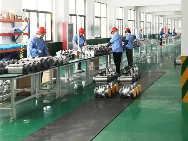
Match valve connections to pipe loads. Good choices bring long life. They stop alignment failures. Right connections give stability. They protect pneumatic butterfly valves well.
Wafer Style for Compact Piping Configurations
Wafer butterfly valves are light. They save space easily. Clamp valves between pipe flanges. Use long tie-rods for this. Use them in tight places. They suit low-pressure utility lines.
|
Design Parameter |
Wafer Body Style |
Lug Body Style |
|---|---|---|
|
Bolting Method |
Uses long tie-rods through flanges |
Uses short bolts into threaded lugs |
|
Thermal Behavior |
Long bolts stretch under heat |
Short bolts reduce thermal expansion |
|
Installation |
Requires strictly even bolt torque |
Allows independent single-sided bolting |
|
Load Handling |
Ideal for standard low-pressure lines |
Resists vibrations and pressure surges |
Lug Style for Dead-End Service and Pipeline Maintenance
Lug butterfly valves have threaded ears. These sit around outer body edges. Bolt the valve to flanges. Each side bolts independently. Disconnect downstream pipes for maintenance. Upstream pressure stays safe inside.
-
Single-Sided Load Endurance: Strong lugs take end loads. They prevent leaks during dead-end service.
-
Enhanced System Stability: Sturdy bodies handle pipe shakes. They stand up to big stress.
Lug butterfly valves speed field repairs. They improve total system lifespan.
Double Flanged and Butt-Weld Options for High-Pressure Lines
Double flanged butterfly valves add strength. They suit big pipes best. Heavy bodies stay lined up. They resist high line stresses. These flanged butterfly valves handle heavy actuators. They will not twist off center.
Engineers pick butt weld models. They use them for hot steam. Butt weld butterfly valves join directly. Weld them right into pipelines. This holds dangerous fluids safely. It removes leak paths completely. Install high-performance butterfly valves for high pressure. Strong butterfly valves stop unexpected shutdowns.
Step 3: Match Wetted Materials to Process Media
Resilient EPDM, NBR, and Viton Seats
Match seat seals to fluids carefully. Check daily line heat limits first. Soft rubber seals shut tight fast. They suit simple daily job sites. EPDM handles clean water safely. It takes low-pressure steam well. NBR stops oil and gas leaks. Viton resists high heat easily. It fights tough fuel chemicals, too. TANGGONG VALVE builds resilient seals. They protect active, heavy-use valves.
High-Performance PTFE and RTFE Chemical Seats
Harsh chemicals need non-reactive fluoropolymer seats. Virgin PTFE and RTFE differ greatly. Check their details below:
|
Material |
Performance under Chemical Exposure |
Performance under Load/Temperature Conditions |
|---|---|---|
|
Virgin PTFE |
Resists strong acid fluids well. It stops harsh liquid solvents. |
Stops high heat damage easily. It deforms under constant pressure. |
|
Reinforced PTFE (RTFE) |
Fillers add good mechanical strength. Glass fillers fail in caustics. |
Reduces high-pressure seal wear. It stops seal shape loss. |
Pneumatic butterfly valves use RTFE seats. They survive tough chemical plants.
Metal-to-Metal Stellite Seats for Extreme Temperatures
Extreme heat needs strong metal seats. Temperatures reach -196°C to 650°C. High-heat metal valves use Stellite 6.
-
Surface Hardness at 650°C: Stellite 6 stays hard at 650°C. Inconel 718 loses strength fast.
-
Wear and Erosion Protection: Hard metals stop particle damage. Discs slide without high wear.
-
Industrial Standard: Stellite sets the main standard. It fights extreme hot friction.
Heavy metal seats shield valves well. They extend total valve life.
Corrosion-Resistant Disc Alloys and Protective Coatings
Match disc alloys to media types. This prevents fast metal pitting. TANGGONG VALVE builds strong discs. We use WCB carbon steel. We also offer CF8 and CF8M. Duplex stainless steel is available, too. WCB steel fits basic lines well. Stainless steel stops chemical rust fast. Duplex metal resists salty ocean water.
You can select protective disc coatings. We apply Nickel or PTFE layers. They shield automated valves from damage. Proper choices keep systems working well. Good alloys maintain valve body strength. Better trims increase total service life. Correct setups protect plant parts fully.
Step 4: Sizing a Pneumatic Actuated Butterfly Valve
Proper sizing needs exact math. Match drive systems to pipe needs. Good sizing stops valve stalling. It also saves equipment money.
Rack and Pinion vs Scotch Yoke Pneumatic Actuators
Pick the right mechanical drive structure. Rack and pinion units handle normal jobs. Scotch yoke mechanisms work better for heavy pipes.
|
Performance Characteristic |
Rack & Pinion Actuator |
Scotch Yoke Actuator |
|---|---|---|
|
Torque Profile |
Flat / Constant throughout stroke (same output at 0°, 45°, and 90°) |
Parabolic / U-Shaped (peaks at 0° and 90°, drops at 45°) |
|
Mechanism Dynamics |
Linear tooth-and-gear engagement |
Sliding pin and variable moment arm |
|
Pneumatic Efficiency |
Lower efficiency; wastes air mid-stroke due to uniform torque sizing |
High efficiency; aligns air consumption with valve torque demand |
Rack and pinion units push with steady force. They give constant output across all angles. This steady force suits simple low-pressure lines. But quarter-turn units need max force at start and finish. Constant units must be oversized for mid-stroke moves. Oversized units waste extra air.
Scotch yoke units use a sliding pin setup. Internal moment arms change size as they turn. This change creates a U-shaped power curve. Torque peaks at 0° and 90° for tight seals. Mid-travel force drops in open fluid. Scotch yoke curves match actual stem resistance needs. This smart curve cuts air use across plants.
Rack & Pinion Torque Curve:   [====================]  Constant Output (0° to 90°)
Scotch Yoke Torque Curve:     [===\____________/===]  U-Shaped Output (Peaks at Ends)
Calculating Breakaway Torque with Safety Margins
Calculate opening force before choosing drives. Closed discs face max force under high pressure. Fluid torque stays at zero when closed. Line pressure creates main opening force.
Calculate breakaway torque with this formula:
-
Total Breakaway Torque Formula: $T_{break} = T_1 T_4 T_3$
-
$T_1$: Torque resulting from seat friction
-
$T_3$: Torque resulting from bearing friction
-
$T_4$: Pressure differential torque component
-
Find pressure torque ($T_4$) using disc sizes and pressures:
-
Differential Pressure Component Calculation: $T_4 = C_d \times \Delta P \times D^3$
-
$C_d$: Dimensionless disc torque coefficient (generally between 0.10 and 0.15 for standard disc geometry)
-
$\Delta P$: Differential pressure measured across the closed disc ($Pa$ or $N/m^2$)
-
$D$: Nominal disc diameter ($m$)
-
Plant air pressure changes during daily work. Main air lines drop pressure at peak times. These air drops lower total actuator output force.
Add a 20% safety margin above calculated torque. Dirty fluid needs a 30% to 40% margin. This margin keeps pneumatically actuated butterfly valves running smoothly. Factory pressure tests confirm these safety limits before shipment.
💡 Sizing Tip: Calculate torque using peak line pressure drop. Adding 20% safety stops valve stalling during pressure spikes.
Double-Acting vs Spring Return Fail-Safe Modes
Choose drive modes based on emergency rules. Double-acting models use air for both directions. Spring-return models use internal springs for auto safety actions.
|
Factor |
Double-Acting Actuator |
Spring-Return (Single-Acting) Actuator |
|---|---|---|
|
Safety / Fail State |
Fails in last position (holds state without power/air) |
Mechanical fail-safe; automatically returns to safe state via spring |
|
Torque Output |
Higher and constant in both stroke directions |
Lower effective torque due to spring resistance |
|
Air Consumption |
Uses air for both strokes (~100% relative baseline) |
Uses ~50% less air (only powers active stroke) |
|
Size & Footprint |
Compact and lighter |
Larger, heavier, and bulkier to fit springs |
|
Upfront & Operating Cost |
Lower initial price; higher long-term energy cost |
Higher initial cost; lower long-term operating cost |
|
Maintenance & Longevity |
Simple seal replacements; fewer parts to wear |
Requires monitoring for potential spring fatigue |
|
Control Complexity |
Requires 4-way solenoid valves |
Requires simpler 3-way solenoid valves |
-
Spring-Return Fail-Safe Reliability: Spring-return setups give total process safety. Strong springs snap butterfly valves open or closed on signal loss.
-
Double-Acting Position Hold: Double-acting units freeze in place if air drops. Trapped air inside holds discs tight.
Drive choices change air use and valve costs. Double-acting units reduce original equipment costs. But double-acting units consume air in both directions. Spring-return units need large bodies for heavy springs. Springs resist incoming air, lowering output torque. Size spring-return models larger to overcome internal spring resistance.
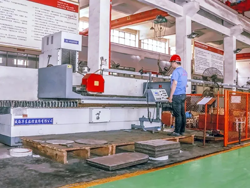
ISO 5211 Direct Mounting and Shaft Compatibility
Standard mounting bases speed up valve setup. ISO 5211 sets main sizes for direct mounting. Direct mounting attaches actuators directly to valve top flanges. This style removes external brackets and loose shaft joints.
|
Standard Connection Category |
Specific Parameters & Specifications |
ISO 5211 Standard Role |
|---|---|---|
|
Flange Dimensions |
Pitch Circle Diameter (PCD), bolt quantity, bolt hole dimensions, and outer diameter |
Establishes structural bolting Alignment between actuator and valve |
|
Centering Features |
Centering spigot/ring (labeled d2) with f8 (shaft) / H8 (hole) tolerances |
Guarantees precise concentric alignment over the stem |
|
Stem Drive Profiles |
Square Drive (Diagonal/Parallel), Double-D (Flat Drive), and Keyed Shaft |
Defines torque transmission geometry to eliminate slippage |
ISO 5211 rules simplify butterfly valve field setups:
-
Flange Size Class (F-series): Standardizes flange thickness, face flatness, and outer diameter across valve lines.
-
Fastener Layout: Standardizes bolt circle sizes and hole counts. This pattern creates even clamping force on stem connections.
-
Concentric Alignment: Uses center holes and tight guide rings. Exact alignment stops shaft bending and protects seals.
-
Drive Engagement: Standardizes stem hole shapes across square, double-D, and key drives. Deep drive shapes transfer full turning force safely.
Built-in direct mounting lowers side pressure on shaft bearings. Direct mounting stops early seal leaks. Factory tests confirm proper stem alignment under pressure. These standardized parts keep pneumatic butterfly valves aligned during heavy use.
Step 5: Essential Automation Accessories
Add smart tools to pipe systems. Upgrade basic pneumatic butterfly valves. Turn them into fine controls.
Solenoid Valves for Fast Directional Switching
Solenoids push air to move valves. Match solenoid types to your actuators.
|
Feature / Function |
3/2-Way Solenoid Valve |
5/2-Way Solenoid Valve |
|---|---|---|
|
Compatible Actuator Type |
Single-Acting (Spring Return) |
Double-Acting |
|
Port Configuration |
3 Ports: Inlet (1), Outlet (2), Exhaust (3) |
5 Ports: Inlet (1), Outlet A (2), Outlet B (4), Exhaust A (3), Exhaust B (5) |
|
Energized Operation |
Directs air from Inlet to Outlet to fill the chamber |
Directs air to Outlet A while venting Outlet B |
|
De-energized Operation |
Cuts air inlet and connects Outlet to Exhaust |
Redirects air to Outlet B while venting Outlet A |
|
Control Mechanism |
Pneumatic pressure drives movement; springs return |
Pneumatic pressure actively drives both directions |
Good air controls protect soft valves. They stop harsh pressure spikes fast.
Electro-Pneumatic Positioners for Flow Throttling
Basic units only open or close. Flow throttling needs precise valve movement.
-
Valve Positioners: Feed loops check main signals. They change internal drive pressure fast.
-
I/P and E/P Converters: Signal tools convert power inputs. They make smooth air pressure outputs.
-
Position Sensors: System sensors check valve positions. They send live data to controllers.
Positioners keep heavy valves open wide. They hold exact flow angles safely.
Limit Switch Boxes and Air Filter Regulators
Clean air stops seal cuts. Filters catch water and balance air. Add extra tools to boost speeds.
|
Accessory / Technology |
Primary Function |
Performance Benefit |
|---|---|---|
|
Quick Exhaust Valves |
Vents compressed air directly into surrounding atmosphere |
Eliminates flow bottlenecks to accelerate deactivation speed |
|
Pressure & Real-Time Sensors |
Delivers dynamic pressure and position data to controllers |
Enables closed-loop monitoring to speed up valve timing |
|
Air Accumulators / Reservoirs |
Stores pressurized air locally within the air system |
Supplies immediate air volume for faster initial actuation |
Boxes show real positions to rooms. These accessories aid offset butterfly valves. Good parts let double offset butterfly valves hold tight shuts.
Step 6: Industrial Uses of Pneumatic Butterfly Valves
Plants use smart tools for tough fluids. Knowing real uses helps you pick tools.
Flow Control and Shutoff Uses
Use a pneumatic actuated butterfly valve fast. High-performance units control hard fluids well.
-
On-Off Shutoff: Zero-leakage triple offset units block high line pressure.
-
Flow Control: Double offset designs change flow levels very smoothly.
💡 Operating Tip: Check pipe pressure drop before picking valves for flow control.
TANGGONG Pneumatic Actuated Butterfly Valve Units
TANGGONG VALVE builds units for hard jobs. Big plants pick our tools for long use:
|
Big Industry |
Main System Jobs |
Key Valve Parts |
|---|---|---|
|
Oil & Gas |
Gas line shutoff and ocean work |
Fire-safe units with strong duplex steel discs |
|
Petrochemical |
Strong acid flow and liquid care |
Tough RTFE seats with body coatings |
|
Power Plant |
Hot steam shutoff and pipe cooling |
Stellite metal seats for extreme heat |
|
Ships & Boats |
Water management and fuel oil lines |
Small wafer and lug bodies for salt water |
Control Angles and Speed Limits
Watch disc angles during flow control. Wrong angles cause heavy pipe shakes.
[0° Closed] --- (20° Minimum) ===== OPTIMAL THROTTLING RANGE ===== (70° Maximum) --- [90° Open]
Keep disc angles between 20 and 70 degrees. Small angles make fluid move too fast. Fast fluid ruins soft valve seats quickly. Big angles lower total pressure control. Good angles protect every disc in your plant.
Pick your pneumatic actuated butterfly valve with care. Check this quick guide first:
-
Valve Function & Size: Follow API 609 rules.
-
Pressure Class & Materials: Match materials to line heat and fluids.
-
Actuation & Testing: Calculate drive force. Demand API 598 tests.
TANGGONG VALVE builds complete pneumatically actuated butterfly valves. Contact our engineers now to check your sizing!
FAQ
What sets wafer valves apart from lug butterfly valves?
Wafer valves sit tight between two pipe ends. Long rods hold these small light units. Lug valves have special screw holes. Bolts turn into each side separately. Pipe crews remove back pipes easily. Front lines hold full fluid push safely.
Why add a 20% safety margin for drive sizing?
Drop in plant air cuts drive output force. A extra 20% torque keeps valves turning. This stops sudden stalls during sharp line spikes. Dirty fluids need 30% to 40% margin.
How do triple offset valves stop all line leaks?
Triple offset shapes move stems off center three ways. Discs touch seats only when fully shut. This smooth action stops bad seat rub. It seals pipelines tight in harsh sites.
Can pneumatic butterfly valves adjust fluid flow levels?
Yes, use special positioners to control fluid flow. Keep disc angles open between 20 to 70 degrees. This safe zone stops fast liquid cuts. It also shields inner seats from quick wear.