



You risk bad downtime. You cannot ignore component sizing. Improper actuator sizing causes problems. It causes 20% of valve breakdowns. Mismatched parts cause valve binding. They cause seat damage. Motors burn out from this. Response times become very sluggish.
Follow strict selection criteria now. Specify your actuated butterfly valve package well. Match your electric actuator carefully. Align it with the valve body. Use these important parameters:
-
Pipeline Factors: Pipe diameter, operating pressure, fluid temperature, and media corrosiveness.
-
Actuator Factors: On-off or modulating control options, torque output, electric power supply, and safety ratings.
Apply these best practices right away. Your electrically actuated butterfly valve will work well. It will operate very reliably.
Key Takeaways
-
System details guide correct valve size choices.
-
This stops frequent machine breakdowns.
-
Offset valve shapes lower seat rubbing.
-
This helps parts last much longer.
-
Extra safety limits stop motor stalls.
-
This helps in tough liquid setups.
-
Matching motor work cycles stops dangerous overheating.
-
This protects parts during non-stop use.
-
Fail-safe settings protect vital pipe gear.
-
This helps during total power losses.
Assessing System Parameters for an Actuated Butterfly Valve
Picking the right automatic valve takes careful work. You must check your pipe system needs first. Do this before you buy any gear.
Pipe Size, Pressure, and Operating Temperature
Your pipe size changes fluid speed. It alters flow resistance too. You must calculate valve size and line pressure. This shows the needed moving force. High line pressure makes big force differences. This force demands more turning force. You need it for quarter-turn movement.
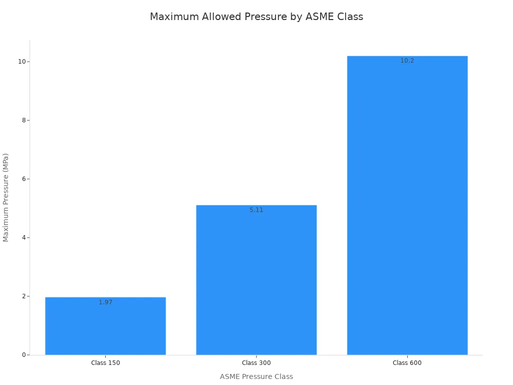
Pressure and heat levels guide body material choices:
|
Material |
Operating Temperature Range |
Pressure Limits |
|---|---|---|
|
Carbon Steel (WCB) |
-29 °C to 425 °C |
Up to PN420 |
|
Stainless Steel (SS316) |
-196 °C to 816 °C |
Corrosive media service |
|
Alloy Steel (WC6, WC9) |
-29 °C to 593 °C |
High-temperature service |
Harsh heat alters seal stretchiness. Cold turns rubber seats hard. High heat ruins soft plastic parts. Choosing resilient seats or metal seats matches hot conditions.
Fluid Characteristics and Media Compatibility
Liquid traits decide part life in tough pipes. Harsh chemicals eat plain metals fast. Hard bits cause rubbing wear.
Note: Solid bits like sand scratch soft seals. This scraping speeds up seal damage. It makes parts fail early.
Gritty liquids cause bad harm in three steps:
-
Solid bits strip protective coatings off inside parts.
-
Fast fluid shows the hidden base metal.
-
Chemical reactions speed up full metal ruin.
You can stop quick wear with strong butterfly valves. Tough butterfly valves handle rough fluids well. Basic butterfly valves fit clean water fine. Muddy flows need strong metal discs. High-performance butterfly valves use special seat materials. They fit tough chemical lines. Picking good parts meets your plant goals. It guarantees a great actuated butterfly valve package.
Selecting Butterfly Valves: Body Styles and Seat Materials
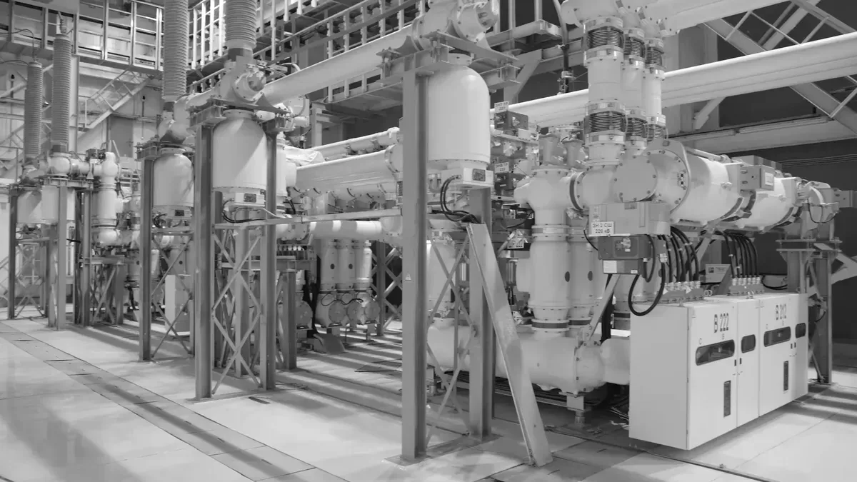
Pick the right valve body shape. Choose good seat materials. Match parts to fluid flow. This stops early system breaks.
Concentric vs. Offset Designs in Butterfly Valves
Concentric butterfly valves center the stem. The stem goes through the disc. The disc edge rubs rubber. Rubbing happens with every move. Offset designs shift stem location. They move the stem back. They move it sideways. This design lifts disc fast. It opens without seat rubbing.
The list shows stem offset effects:
-
Concentric (Zero Offset) Design: Stem centers on disc. Disc touches seat fully. Contact stays for whole turns. Friction causes quick part wear.
-
Triple Offset Design: Cone shape guides the disc. Disc moves like a cone. Disc swings without rubbing seat. It touches seat at end. This action stops all rubbing.
This table compares seating stats:
|
Functional Metric |
Concentric Butterfly Valve |
Triple Offset Butterfly Valve |
|---|---|---|
|
Sealing Mechanism |
Constant friction / soft seat shape changes |
Angle contact force via cone shape seating |
|
Seat Friction Level |
High friction from constant stroke rubbing |
Zero friction during valve movement |
|
Wear Characteristics |
Subject to fast surface wear |
Zero wear due to final contact |
|
Operational Seat Lifespan |
Short life for low pressure |
Long life for high pressure |
Pressure limits divide valve types:
|
Valve Design Type |
Primary Operational Pressure Limit |
|---|---|
|
Concentric (Resilient-Seated / Zero Offset) |
Up to 250 PSI |
|
High-Performance (Double Offset) |
Up to 1440 PSI |
Double offset butterfly valves control low-pressure flow. They use a body stop. They rely on position seating. This setup needs less force. Triple offset models use torque. They need high closing force. Thus, double offset valves save energy. They suit automated flow control.
Wafer, Lug, and Flanged Body Styles
Pipe connections change setup steps. Wafer, lug, and flanged options give clear perk sets.
Wafer butterfly valves are compact. They take up little pipe space.
-
Weight Efficiency: Low weight reduces pipe strain.
-
Space Efficiency: Short body fits tight spaces.
This table compares weight and size:
|
Body Style |
Installation Weight |
Required Pipeline Space |
|---|---|---|
|
Double-Flanged |
Heavy design adds pipe weight |
Needs big space for setup |
|
Wafer |
Light weight from thin build |
Small size fits tight spots |
Lug models fit dead-end lines. Wafer models cannot do this. Lug designs hold threaded inserts.
|
Feature / Valve Style |
Lug-Style Butterfly Valve |
Wafer-Style Butterfly Valve |
|---|---|---|
|
Mounting Mechanism |
Uses threaded lugs for pipe flanges. |
Clamps between two flanges with bolts. |
|
Dead-End Service Suitability |
Suitable: Works at pipe ends safely. |
Unsuitable: Cannot isolate pipe ends. |
|
Impact of Removing Piping |
One side unbolts for easy repair. |
Removing pipe releases all clamp force. |
TANGGONG VALVE builds all body styles. Sizes range from DN40 to DN3000. These options fit big industrial jobs.
Resilient vs. Metal Seat Materials
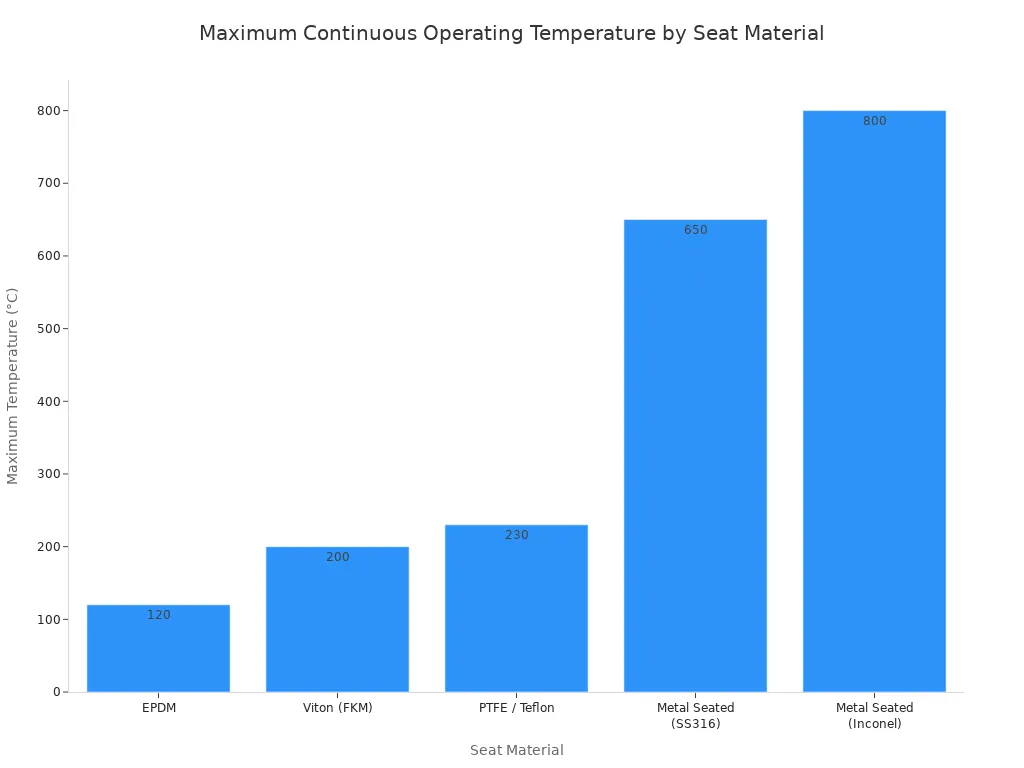
Seat materials control heat limits. They change fluid resistance. They affect seal tightness. Soft seats block clean liquid flow completely. Metal seats handle sudden heat. They stop coarse fluid damage.
This table shows heat limits:
|
Seat Material |
Maximum Continuous Operating Temperature |
|---|---|
|
EPDM |
120°C (250°F) |
|
Viton (FKM) |
200°C (390°F) |
|
PTFE / Teflon |
230°C (450°F) |
|
Metal Seated (SS316) |
650°C (1200°F) |
|
Metal Seated (Inconel) |
800°C (1470°F) |
Seal standards vary by seat type:
|
Application Category |
Standard |
Resilient (Soft) Seat Requirement |
Metal Seat Requirement |
|---|---|---|---|
|
Isolation / On-Off |
API 598 |
Demands absolute zero leakage |
Allows fixed small fluid leaks |
|
Modulating / Control |
ANSI / FCI 70-2 |
Class VI: Low bubble count limit |
Class IV: Max 0.01% flow leak |
TANGGONG VALVE makes custom butterfly valves. Options include EPDM, Viton, PTFE, RTFE, and Inconel. Build tough butterfly valves easily. Keep seals working well.
Actuator Sizing for an Electrically Actuated Butterfly Valve
Pick motor parts with care. Big units waste money. Small motors fail fast. They cause bad seat wear. Systems stop running suddenly. Calculate forces to build reliable butterfly valves.
Calculating Operating Torque and Safety Margins
Valves need force to move. We call this force torque. Highest force happens at start. Size motors to overcome it. This initial push is breakaway torque.
System conditions change turning resistance over time:
|
Stage / Operational Factor |
Mechanical Impact on Valve |
Effect on Breakaway Torque & Performance |
|---|---|---|
|
Particle Intrusion |
Dirt enters sealing areas. |
Increases moving force needs. |
|
Deposit Accumulation |
Material coats the seat. |
Raises friction and blocks turns. |
|
Component Wear |
Harsh bits rub parts. |
Ruins surfaces over time. |
Dirty liquids demand double motor torque. Dirt gets stuck in seats. Thick fluid turns hard. Extra power breaks static stick.
Tip: Add safety extra to base stats. Makers suggest 25% to 50% more power. Multiply base torque by 1.25 to 1.5.
Choose extra power based on fluid:
|
Fluid / Operating Condition |
Recommended Safety Margin |
|---|---|
|
Clean liquids |
20% to 30% |
|
Dry gas, slurries, or rarely cycled valves |
Up to 50% |
Calculate power using basic rules:
-
Standard Clean Fluids: Add 20% to 30% safety force.
-
Slurry or Viscous Media: Add 50% extra force to stop stalls.
TANGGONG VALVE shares exact torque data sheets. Combine line pressure and friction data easily.
Power Voltage and Motor Duty Cycle Options
Match plant power with correct motor needs. Systems use DC or AC power. Options include 24V DC, 110V AC, and 380V AC.
Choose motors that suit work speed. Fast motion heats motor cases. Basic motors overheat under constant control. Match duty stats to process loops.
Industry uses standard duty classes:
|
Service Application |
Required IEC Rating |
NEMA Equivalent |
Operational Characteristics |
|---|---|---|---|
|
Standard On/Off Isolation |
S2 (Short-Time Duty) |
Intermittent Duty (15/30-min ratings) |
Runs briefly then cools down. |
|
Standard Modulating Control |
S4 (Intermittent Periodic Duty) |
N/A |
Starts often for control loops. |
|
Continuous / Severe Process Control |
S1 (Continuous Duty) |
Continuous Duty |
Runs non-stop without hot damage. |
Simple tasks need basic short duty motors. Flow control demands tough S1 drives. High duty units stop heat damage. They keep an electrically actuated butterfly valve running smoothly.
Specifying an Actuated Butterfly Valve Package for Automation
You need correct parts now. Pick them for your valve package. Industrial sites use smart controls. These give fast responses.
On/Off vs. Modulating Flow Control
Choose basic open-close moves. Or pick precise flow control. On-off jobs use standard electric actuators. They shift butterfly valves wide or shut. Modulating systems use an electric actuator. It moves butterfly valves to middle spots.
|
Differentiating Feature |
On/Off Isolation Actuator Package |
Modulating (4-20mA) Control Actuator Package |
|---|---|---|
|
Core Control Logic |
Uses limit switches to stop the motor at full open or closed points. |
Integrates a digital valve positioner for precise real-time flow adjustments. |
|
Position Sensors |
Basic open/closed status limit switches. |
Magnetic sensors detect exact stroke percentages. |
|
Motor Duty Cycle |
Rated for intermittent operation (S2 standard). |
Uses high-duty motors (75%-100%) for frequent adjustments. |
|
Signal Interface |
Discrete digital voltage inputs. |
Analog 4-20mA current loops for fine control. |
Smart controllers process signals well. They check loop stability needs. Advanced modulating butterfly valves give accurate control. They work great in high-flow pipes.
Fail-Safe Mechanisms and Position Feedback
Power loss brings big danger. Check safety needs before setting valves.
-
Mechanical springs offer high safety. They push valves to safe spots.
-
Battery units use internal power. They shut valves during outages.
|
Performance Metric |
Mechanical Spring Return |
Battery Backup (BSR) |
|---|---|---|
|
Fail-Safe Reliability |
Highest (Operates via pure mechanical force) |
Moderate (Relies on internal electronics) |
|
Response Speed |
Fast (Reaches safe position in 2–31 seconds) |
Slower (Restricted by normal motor speed) |
Meet strict safety needs easily. Use an electrically actuated butterfly valve. Add emergency spring parts. These units guard plant equipment fast.
Remote tracking needs solid feedback. Select flexible electric features to track positions:
-
Digital network setups: Modbus RTU, Modbus TCP/IP, HART, Profibus, and Foundation Fieldbus.
-
Magnetic switches for easy tuning. No opening of covers needed.
-
Dry contacts to send status updates. They alert main control rooms.
These electric setups stop costly downtime. They boost safety for all butterfly valves.
Environmental Ratings and TANGGONG VALVE Solutions
Enclosure Protection and Hazardous Area Ratings
Choose strong electric covers for tough plants. Outdoor spaces need IP67 or IP68 water protection. Dangerous sites need ATEX or NEMA proof housings. These heavy covers guard drives from dust and gas. Good electric parts stop inner heat build-up. Safe electric gear shields workers in all jobs.
ISO 5211 Mounting and TANGGONG VALVE Capabilities
Direct setup needs ISO 5211 rules. Standard pads line up the shaft directly. This tight fit ensures great control without bending. Straight alignment makes all butterfly valves last long.
TANGGONG VALVE makes strong butterfly valves for plants. Our design meets tough site rules for big tasks. Custom builds fit special hot or cold limits. We build top butterfly valves in big sizes. Put our tough butterfly valves in pipe lines.
Our top plant builds sturdy butterfly valves well. We supply high-performance butterfly valves for plants. Count on us for every butterfly valve package. TANGGONG VALVE sells versatile butterfly valves for all:
|
Certification Name |
Focus / Purpose |
Application Area |
|---|---|---|
|
ISO 9001 |
Quality Management Systems |
Ensures uniform manufacturing and product quality |
|
Fire Safe API 607 |
Fire Safety Compliance |
Critical use in petrochemical and industrial pipeline environments |
|
CE (PED) |
Health, Safety, and Environmental Standards |
Required for entry and deployment in the European market |
|
ISO 14000 |
Environmental Management |
Guides sustainable and eco-friendly manufacturing practices |
|
TS Manufacture License |
Special Equipment Regulatory Compliance |
Mandatory state certification for special equipment production |
|
Industry Specific (ACS, AWWA, ATEX, Maritime) |
Sector-specific safety and operational criteria |
Potable water systems, water distribution, explosive zones, and marine environments (DNV, ABS, CCS, LR) |
Pick our great butterfly valves for your job. TANGGONG VALVE offers top flow gear today.
Pick your valves using simple steps. Protect your pipes using these smart tips:
-
Find the exact starting torque and running torque.
-
Pick the right electric power supply and controls.
-
Match your valve stem with a strong actuator.
Check system pressure charts against valve maker torque data.
Correct torque numbers improve plant safety. Good torque output stops machine failures. Top butterfly valves improve daily flow control. Strong butterfly valves lower repair costs. Good butterfly valves give long service life.
FAQ
How do you find the force needed for an electric actuator?
You find force by checking movement resistance at high pressure. Always multiply this base force by a safety factor of 1.25 to 1.50. This extra force buffer stops motor stalls during sudden pressure spikes.
How do concentric and offset butterfly valves differ?
Concentric designs center the stem inside the disc. This causes constant rubber seat friction during turns. Offset butterfly valves move the stem back. This lifts the disc off the seat instantly. Offset models handle higher pressure easily. They reduce mechanical wear across heavy industry jobs.
|
Design |
Sealing Type |
Friction Level |
|---|---|---|
|
Concentric |
Rubber contact |
High friction |
|
Triple Offset |
Metal-to-metal |
Zero friction |
How do fail-safe electric actuators work without power?
Fail-safe actuators move butterfly valves to safe positions automatically during power loss. Mechanical spring-return units release stored force right away. Internal battery systems give temporary backup power instead. This runs the motor to your safe spot.
What signals control variable fluid movement?
Variable control systems use 4-20mA current signals. They also use 0-10V DC signals. These signals adjust stem positions with great care. Modern digital networks like Modbus RTU send precise movement commands too. These live inputs help your PLC control fluid flow across automated pipelines.
Why do fluid traits affect seat choices?
Gritty fluids, harsh chemicals, and hot heat destroy wrong valve seals fast. Standard soft seats handle clean water well. Heavy slurry lines need strong metal seats. These seats stop wear and keep processes safe. They also ensure long working life.